
For a long time I've exclusively run Lucent Technologies Orinoco Gold (PC24E-H-FC) WiFi cards for my Wardriving mobile. But, since Netstumbler 0.4.0 and Windows XP, it's never been stable for more than a few minutes, now using three different computers, two different cards, and three different operating systems. No matter what things I've tried from reading on stumber.com, netstumbler.org and a myriad of other websites, Stumbler seems to lose access to the cards after periods of seconds to minutes to tens of minutes, with the program merrily thinking that the card's just not seeing anything. The only way out of this is to physically remove and reinsert the card. 9 times out of 10, that solves the problem for a period of time. I've killed the dreaded Windows Zero Wireless Configuration service, I've tried to characterize the stoppages in case it was certain types of access points that would hang the card, changed the card drivers, etc., but no luck.
The following modification/hack will void the warranty on the card.
TOOLS AND OTHER ITEMS REQUIRED FOR THIS HACK/MODIFICATION
Sharp Xacto
blade
Very fine gauge, low temp soldering iron
Fine gauge solder
fine needle nose pliers
RG188 or RG174 50cm coax pigtail with desired antenna connector attached
to one end (I like N female)
fine wire cutters
fine solder wick
silicone adhesive
small work vise
Magnifying lens (parts are very small)
courage or foolishness...
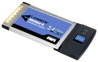
I just went out and bought a Linksys WPC11 (on sale for $39 including rebate) and proceeded to install an external antenna. It's very simple, actually. With an Xacto knife, I popped loose the bottom side of the black plastic antenna cover just by running the blade around the fine line separating the two halves. The bottom side comes off easily, it hinges away from the top piece, and with a gentle urging, it separates from the lower sheet metal body by rocking it back and forth along the hinge line.
That's only half the battle. Neither the antenna nor the transceiver circuitry are exposed by this action. The harder part is to remove the upper black antenna cover. This requires a bit more daring, with several actions required before this piece yields. Done carefully (and I can be a bull in a china shop) it takes just a few hair-raising minutes...
There are two specific things that must be done to loosen the top from the upper sheet metal body piece. First is to run the sharp Xacto blade along the separation joint between the upper and lower metal pieces, to get them to separate just enough that the metal body parts can be separated about 10mm at the antenna end. This won't happen immediately; the second movement needs to be performed. There are 4mm slots in the black top antenna piece into which tabs from the upper metal body fit. These tabs have a sprung "tine" of metal that acts to latch the lower body to the upper body through these slots, and to securely hold the upper antenna body rigidly in place. Carefully insert the blade into the slot, and gently ease the upper metal piece's tabs free from the slot and from the lower body. There may be some collateral damage to the tabs, which I fixed before reassembly.
Like I said, this is not an easy exercise, requiring the blade to go back and forth between the effort of separating the metal halves, and getting the tabs out of the upper plastic antenna cover. But, with patience and a few minutes of effort, the assembly finally comes loose and the upper plastic antenna cover may be removed, again by urging it loose from the upper metal body. Now, I clean up the possibly bent metal tabs with a small needle-nose pliers, restoring them to their original flat and undistorted shape, and ensuring that the small metal tines in the middle of the tab lay just out of the plane of the tab itself in order to allow them to once again be able to engage both the plastic cover and the lower metal tabs.
Now I have two pieces of black plastic, and the rest of the WPC11 kinda splayed apart, open most at the antenna end. The next steps require the magifying lens, a very small tipped soldering iron, fine tweezers, the Xacto blade and very small gauge solder.
I note that in the center of the board there is a trace that comes from the transceiver circuitry, passes through two capacitors (0102 size, I think), then doglegs left and goes to a gamma-matched antenna printed on the left edge of the board. (with the card's label up, PCMCIA connector toward me, the left is on my left...) I notice that the second capacitor (PCxx) looks like it could be turned 90 degrees to hook up to another circuit trace that heads due left to a small solder pad otherwise unconnected, and adjacent to two ground solder pads. These pads are where I will attach the small coax cable that will ultimately snake out of the case to an external connector.
Here's tough step 1. I need to unsolder that second capacitor, rotate it 90 degrees, and resolder it to close the second circuit. Solder wick, a fine-nosed iron, and an Xacto blade gently placed will get the part loose. I twist the part 90 degrees and resolder it, one end to one of the original pads, the other to the preciously unused pad to the left. It does not matter what orientation this capacitor has (has no concerns over rotation or endedness), I just manage to get it back onto the board without losing it...
Now, I take the small coax, strip the end, twist the outer braid into a very tight pigtail, and ensure that the center conductor is tightly twisted if stranded. I cut both pigtails to about 3mm each, then tin with solder and cut again to about 2mm length. I arrange the outer braid pigtail in-line with the coax, and the inner conductor with a sharp 90 degree bend. Now, I solder the braid first to either or both of the ground pads, and then next solder the center conductor to the pad just to the left of the repositioned capacitor. I add a dab of silicone adhesive to bind the coax to the board just before the end and let it cure.
I take the lower antenna cover and with the Xacto blade notch out a passage no wider than the coax, aligned precisely with the coax. I do the same to the upper antenna cover. Now, I reattach the upper antenna cover to the upper metal body part, gently fitting the metal tabs back into the slots. As I do this, I have to make sure that the coax is properly dressed out through the notch I've cut into the antenna cover, and just before the whole thing goes back together, add a good sized dab of silicone to secure the coax to the board and to the antenna cover. Once cured, this will ensure that there's a decent strain relief to the coax. I replace the lower antenna cover, and gently re-engage the upper and lower metal body pieces while making sure that the tabs stay well seated in the upper antenna cover. Also make sure the lower metal tabs engage the slots properly.
The whole thing needs to sit overnight to cure the silicone. Once that's done, I've now got an external connector for my WPC11, and have found that its perfornance is essentially the same as my Orinoco card with its factory-installed connector. I've compared it to the Orinoco setup using a standard external antenna, and have discovered to my satisfaction that the number of APs captured in any of my normal test runs remains within a few percent (i.e., my neighborhood currently has about 65-67 APs as measured by the Orinoco, with the hacked WPC11 I just measured 65 APs. So I call that good enough for government work...
Remember that this modification voids any chance of warranty repair for the card.
One very interesting thing about using this card with NetStumbler. There appears to be some disconnect between Stumbler and the card, since the access point names that show up on Stumbler seem to hop in real-time between multiple MAC addresses. Also, given enough time, most access points will ultimately show up on ALL radio channels. Now how that works, I don't know. I suspect that NS and Linksys are not cooperating in some substantial manner.
Railroading - Cool Links - Work - Words
Mountain Biking - jonCams - Thesis - WiFi
Copyright
© 2003 Jon Trent Adams
jon (at) jonadams.com